Kawasaki KLR Forum banner

Gen 1 Ignition on Gen 2

36K views 65 replies 7 participants last post by  PeteK  
#1 · (Edited)
I've been building a bare-bones harness for the '09. It has been stripped of unnecessary stuff and designed to integrate with the Vapor dash and HID headlights. That project has been on the back burner while I worked on the kick start stuff.

Now it looks like I'll put a Gen 1 ignition in the '09, so the bare bones harness will be modified to accommodate that stuff.

With thanks to Damocles for his help on the Gen 1 vs Gen 2 ignition differences, I think I have a plan. This still needs to be traced out at least two more times, but the scope of the project is set.

I'm going to pay a visit to Bothwell Automotive and see if they can balance a Gen 2 Rotor. I'll give it one shot. If they can I'll modify the Gen 2 rotor for use with the Gen 1 ignition. If not, I'll use the Gen 1 rotor.

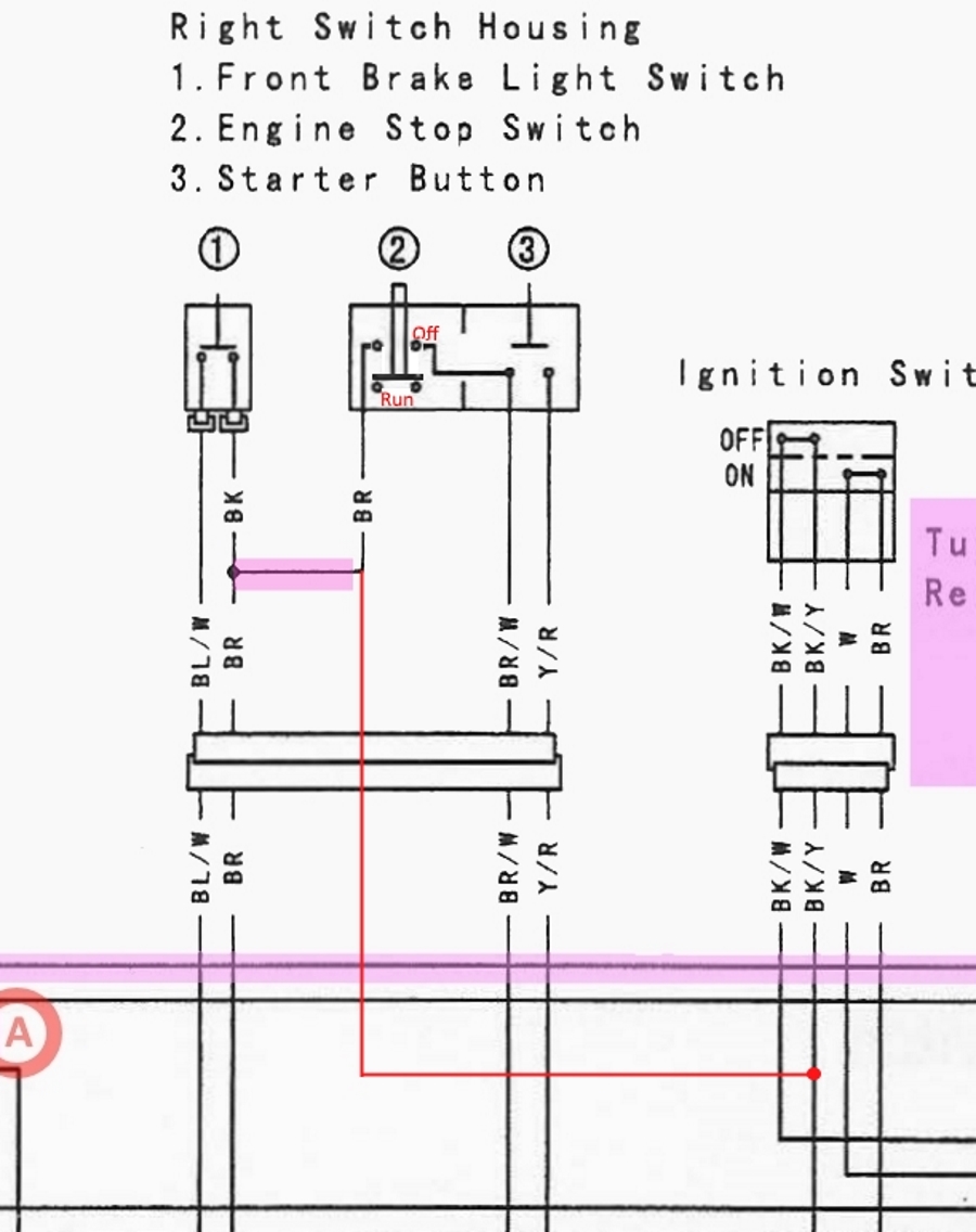
Here's my first crack at the modified wiring. Purple goes away, red is added.
Image


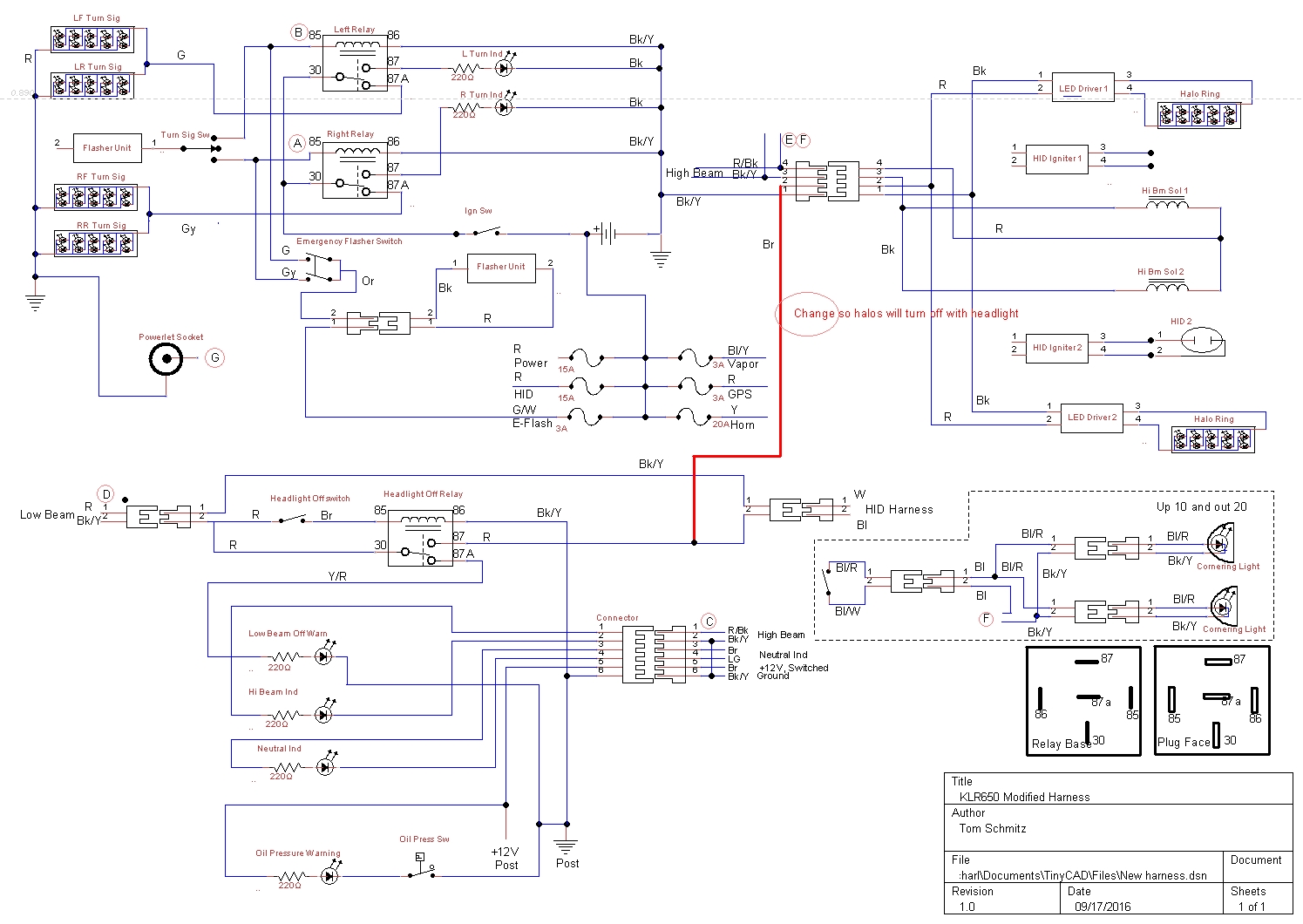
For competeness, this is the wiring diagram for all the new Vapor, HID, Turn/Emerg, etc that the harness interfaces with.
Image
 
#2 ·
Only cursory examination of truly excellent wiring diagrams, but . . . don't see ENGINE STOP SWITCH logic . . .

Both IGNITION SWITCH and ENGINE STOP SWITCH use GROUNDING of exciter coil lead to CDI as kill mechanism on Generation 1s (vs. opening of + 12 VDC lead to igniter on Generation 2s).

So, ignition switch (and engine stop switch, if any) might bear watching, with trans-generational ignition conversion.
 
#3 · (Edited)
It is very hard to see on the schematic unless you open the file in a new tab and zoom in.

I've enlarged the section; see if it looks logical to you. The kill switch will work 'backwards', the 'Off' position will be 'Run'. The ignition switch looked OK as-is.
Image
 
#4 ·
Eh, not so fast, sport.

The ignition switch might be a problem and the starter button is a problem.

This will require pondering.
 
#5 · (Edited)
Damocles,

The Gen 2 ignition switch performs the same base functions as the Gen 1 switch. That is, it connects the white 20A B+ to the switched power, brown, when "On" and grounds the igniter when "Off". It does not have the "Park" position and doesn't control the headlight power, etc., but that seems to be no matter. I think it will work as-is.

The starter switch on the Gen 2 takes it's power from the kill switch on the Gen 2. The kill switch is a SPST. The kill switch on the Gen 1 is a DPST and serves to ground the igniter and provide power to the starter switch. In order to avoid diodes, relays, and magic dust I think I need to leave it alone. Thus, I will not have a kill switch because, as you pointed out, the kill switch on the Gen 2 interrupts power to the coil rather than grounding the igniter.

What do you think the effect and ramifications of using the Gen 2 kill switch would be if it were used to interrupt power to the Gen 1 coil?

I can live without a kill switch, but I wonder if I need to lock its position so that it can't be moved, or perhaps go into it and hardwire its function.

There's an extra right-side swtich block around here that I'm going to dissect and see how the internal wiring is accomplished. Might be I could still make it work...
 
#6 ·
Didn't know the Generation 2 ignition switch grounds the igniter when OFF; opening the circuit to the coil primary windings was its function, I thought.

What do you think the effect and ramifications of using the Gen 2 kill switch would be if it were used to interrupt power to the Gen 1 coil?
My concept (unverified at this moment) is: The Generation 1 ignition coil is never physically "disconnected" from the stator exciter coils through the CDI, which discharges its capacitor from pickup coil pulse; however, the CDI power lead is grounded when the kill switch is in the OFF position (if there IS a kill switch) or the ignition switch is in the OFF position (again, Generation 1 OEM configuration).

You may be able to, "re-purpose" the kill switch to interrupt the circuitry between the CDI and the ignition coil primary windings, but keep in mind you're dealing with voltage determining spark intensity; you'll need a solid, low-resistance connection when the kill switch is in the RUN position.
 
#7 ·
Didn't know the Generation 2 ignition switch grounds the igniter when OFF; opening the circuit to the coil primary windings was its function, I thought....
We have to qualify my statement with "That's the way I'm reading it", which could be wrong.

In the "Off" position the Gen 2 ignition switch connects the B/W from the igniter to chassis ground, the B/Y ground bus wire. Of course, we don't know the functions of the various igniter pins because Denso and KHI hold these close to the vest, but I take that as "grounding the igniter".

I cannot find the right side switch block anywhere in the Shed of Horrors, which is why it is called the Shed of Horrors. I am leaning towards not having a kill switch.

Obviously, I must study this much more...
 
#8 ·
A Western Power Sports #57-5012 kill button to fit Yamaha YZ dirt bikes is a nice momentary button for kill or horn. It has about 18-20 inches of 2 wire leads on it.
 
#9 · (Edited)
The OEM kill switch, of course, is more-than-momentary . . . yet; truth be told, I have never been in a situation where a kill switch was of critical importance, myself (doesn't mean they don't occur).

Jimmie Lynch, of the internationally-famous Death Dodgers auto thrill show, lectured: When an automobile is upset/overturned with the engine running, a better idea than immediately shutting the motor off, is to let it run, preventing combustible mixture from contact with a hot exhaust manifold, creating a fire (from the days when automobiles had carburetors).

He also said, the BEST tires should go on the REAR wheels, because . . . the driver had some control over a front-tire blowout from the steering wheel; none for the rear tires . . .

Guy had some credibility; had been in LOTS of crashes, for fun and profit! :)

Jimmie Lynch even took Mr. Wiffle, of, "Don't squeeze the Charmin" fame, for a ride:


I digress. Moderators, delete any or all contamination of the website with clear conscience, if you must! :)
 
#10 ·
The Gen 1 and Gen 2 coils are different, that we know.

The Gen 2 coil has no marking as to '+' or '-'. The Gen 2 does.

Both coils have a wide tab and a skinny tab. On the Gen 2 the skinny tab is connected to the black wire that goes to the igniter.

Now, it seems obvious and a dumb question, but I have to check.

In the Gen 1 harness is the skinny connector connected to the black wire that goes to the CDI? In other words, is the '-' side of the coil connected to the CDI?

I should think they would be wired the same buuut....
 
#15 ·
The Gen 1 and Gen 2 coils are different, that we know.

The Gen 2 coil has no marking as to '+' or '-'. The Gen 2 does.

Both coils have a wide tab and a skinny tab. On the Gen 2 the skinny tab is connected to the black wire that goes to the igniter.

Now, it seems obvious and a dumb question, but I have to check.

In the Gen 1 harness is the skinny connector connected to the black wire that goes to the CDI? In other words, is the '-' side of the coil connected to the CDI?

I should think they would be wired the same buuut....
Tom, Which has What?

On a Gen 1 ignition coil the inward skinny tab is the Black/Yellow Ground terminal. Primary contact tabs face towards the rear of the bike.

I do believe polarity does make some difference on both systems. Not sure how much difference.
 
#11 · (Edited)
Inconvenient to examine my Generation 1, but . . . going out on a limb, I think possibly (not unlike with a non-directional tire), the polarity of the primary ignition coil leads may be interchangeable, with the corresponding ignition system.

The CDI discharges a capacitor across the primary windings when firing the plug; primary and secondary windings are connected to the CDI; no rectifier obvious between CDI and ignition coil; thus . . . don't think polarity involved. If so, don't see damage possible if wires are reversed; if coil won't fire one way, re-connect with reversed polarity and see what happens!

(I know; I know: Easy for ME to say! :) )

One side of the coil primary winding goes to ground; the other to the CDI (and to one side of the secondary coil winding). Don't think it matters, which is which, but don't know this for a fact.

With the ignition coil installed and connected, you might look at the manual test procedure to see if you might be in the ballpark:

Clymer, Generation 1, says: Primary: 0.15-0.21 ohms; Secondary: (between spark plug lead and BLACK/YELLOW wire terminal) 3.8-5.8 K ohms.

Good luck!
 
#13 ·
Glad you enjoyed it, shinyribs!

Regrets to any members if my use of the kill switch consideration to justify the Jimmie Lynch "off-topic" clip offends.

I actually met Jimmie Lynch, shook his hand, just before he gave the safety lecture I referenced.

Now, back to the regularly-scheduled kick-start program! :)
 
#17 ·
Back in the day when I worked on points/coil ignitions on cars it was important to have the coil polarity correct. If it wasn't the spark would jump FROM ground TO the center electrode on the sparkplug as well as creating a weaker and intermittent spark and rough running engine. I don't know for sure if this applies to the KLRs but it might....
There was a way to check the spark polarity, I'm going to see if I can find it in one of my old manuals.

JJ
 
#18 ·
The TCBI on the Gen2 is very similar to a 'breaker points' system. With-out the 'Mechanical' breaker points.

The CDI systems always leave me 'scratching my head'. And CDI has been in-use almost 50 years!
 
#19 ·
You Guys will love this!
1)Remove the spark plug lead and hold it about 1/2" or less away from the spark plug. The spark needs to jump from the lead to the plug which is still screwed into the head.
2)WEARING A HEAVY GLOVE hold a sharpened pencil between the lead and sparkplug so the carbon pencil point is in the path of the spark.
You will be able to SEE which direction the spark is coming from, the lead or the plug.
Correct is from the lead to the pencil point then to the sparkplug. Incorrect is from the spark plug to the pencil point to the lead.
I kid you not, there is even a diagram. I wish I could post it for you all!
In the "correct polarity" diagram the spark from the lead to the pencil point is shown solid and strong, then from the pencil point to the plug as weaker and dispersed.
In the "incorrect polarity" diagram the spark from the plug to the pencil point is shown as solid and strong and from the pencil point to the lead as weak and dispersed.
Though procedure is for a points ign system I don't see why the spark polarity test wouldn't work on any ignition type.
JJ
 
#20 ·
Yeah, that's the way we used to do it when setting up the ignition on British four-bangers. It looks good in the diagram, sort of the like the drawings in the back of Boy's Life that showed you how well the Easy Off Pimple Popper worked, but in real life it's hard to see the flare.
 
#23 ·
Damocles,
You forgot the Gen 1 coil mounting tab is 'plastic', therefore the only ground is the ground terminal.

JJ,
Not to confuse the 'best polarity discussion' for our single cylinder engine, but dual lead coils used on say almost all 4 cylinder motorcycles that I've ever been around, fire one lead positively and the other lead negatively, at the same time.
The twin plug per cylinder Kawasaki Vulcan V-twins 750's / 1500 / 1600, do the same.
So we will see the center electrode erode more on say the Left spark plug and the side ground electrode erode more on the Right spark plug. If we were to re-gap the spark plugs and reverse the primary polarity, we could even-out the erosion. :)

But that does sound like a cool trick with the pencil. One can use said pencil to draw a line or 2, to ground inside an old fashioned distributor cap and Create a mis-fire on a Fresh Tune-up job.
 
  • Like
Reactions: justjeff
#29 · (Edited)
Jeff,

Paul says that the skinny tab on the coil is connected to chassis ground with a BK/Y wire and the fat tab is connected to the CDI box. That is backwards from how the Gen 2 is, where the skinny tab goes to the igniter.

Thus, I have to change the terminals around on my harness. In electronics/electrical work the most common (and standard) connectors are .250" and .187", followed by .110". Can you guess what the skinny tab one the coil is? It's .205". Ya know what the onliest thing in the world (besides some stupid git's idea of an ignition coil) that uses .205" connectors?

Audio speakers and video game crap.

A smart person would file the .205" down to .187" and POR.

So I ordered .205" FASTON connectors from Mouser...
 
  • Like
Reactions: justjeff
#30 ·
The rotor and stator have been installed. CDI fits in the Gen 2 bracket if the tabs are spread just a bit.

A simple adapter plate to mount the Gen 1 coil in the Gen 2 bracket.
Image

Image


The simplified and adapted harness is ready for trial fitting and testing for function, then final wrapping.
Image
 
  • Like
Reactions: justjeff
#32 ·
Jeff,

When it comes to ignition stuff, Damocles explains it best.

For optimum operation, you must have a GENERATION 1 ignition coil to function with a respective ignition system consonant with that generation.

Why? Generation 1 ignition coils function more as TRANSFORMERS, while Generation 2 ignition coils are more like INDUCTORS. If you check the resistance specifications of the two components, you will see a considerable variation between them.

The Generation 1 ignition coil transforms a high-voltage DC pulse from the CDI module's capacitor to an even higher voltage, firing the spark plug. No current flows in the primary windings until the capacitor is discharged by the pickup coil output triggering the thyristor discharging the capacitor. Current flows in the Generation 1 ignition coil for only an instant, when the spark plug fires.

By contrast, the Generation 2 ignition coil primary windings receive power immediately when the ignition switch is turned on. The primary ignition coil windings around an iron core are saturated by this battery current 'til the pickup coil abruptly terminates this power; the consequent rapid decay of the electromagnetic field created by the battery current induces a voltage into the secondary windings; the resulting high voltage fires the spark plug....
 
  • Like
Reactions: pdwestman
#34 ·
It all works just fine. It's pretty straightforward. The only thing that could trip one up is that there is a 100Ω resistor in the ignition switch between the B/W and the B/Y wire that the manual doesn't mention. I was perplexed at seeing a 100Ω path to ground when I was doing a double check of all the wiring just after installing the new harness. Had me going for an hour or so, as I my first thought was that I had a ground pin in the wrong spot on some on one of the running light connectors or one of the connectors to the relays crossed up.

The B/W needs to be disconnected from ground (open, infinite resistance) when the ignition switch is in the "On" position in order for the CDI to operate. Grounding the B/W is what kills the ignition when the switch is turned to "Off".

It would have seen 100Ω path to ground as a ground, so the resistor had to come out.

I added a switch to connect the Y/R wire to B+ when kicking. I don't know if it is strictly required on the Gen 1, but it can't hurt.
Image


A genuine Shindengen MOSFET FH020AA was added in at the last minute. The LiFePo batteries are supposed to be happier being charged by the MOSFET regulator/rectifiers.
Image


All that's left is to do the final wrap in the new harness, reinstall it, and button everything back up.
 
#40 ·
It all works just fine. It's pretty straightforward. The only thing that could trip one up is that there is a 100Ω resistor in the ignition switch between the B/W and the B/Y wire that the manual doesn't mention. I was perplexed at seeing a 100Ω path to ground when I was doing a double check of all the wiring just after installing the new harness. Had me going for an hour or so, as I my first thought was that I had a ground pin in the wrong spot on some on one of the running light connectors or one of the connectors to the relays crossed up.

The B/W needs to be disconnected from ground (open, infinite resistance) when the ignition switch is in the "On" position in order for the CDI to operate. Grounding the B/W is what kills the ignition when the switch is turned to "Off".

It would have seen 100Ω path to ground as a ground, so the resistor had to come out.

I added a switch to connect the Y/R wire to B+ when kicking. I don't know if it is strictly required on the Gen 1, but it can't hurt.
Image


A genuine Shindengen MOSFET FH020AA was added in at the last minute. The LiFePo batteries are supposed to be happier being charged by the MOSFET regulator/rectifiers.
Image


All that's left is to do the final wrap in the new harness, reinstall it, and button everything back up.
Tom, how did you remove the resistor from the ignition switch? Was it easily accessed when you opened up the plastic sheath around it's wires? I received all of the parts for the gen 1 ignition conversion and this is my first task to make sure these parts work before the kickstart addition and then wire harness minimizing/starter delete.