
What year are you riding? How many miles? What oil (be specific) you useing? HERE is the BIGGEY, WHAT TEMPERATURE?
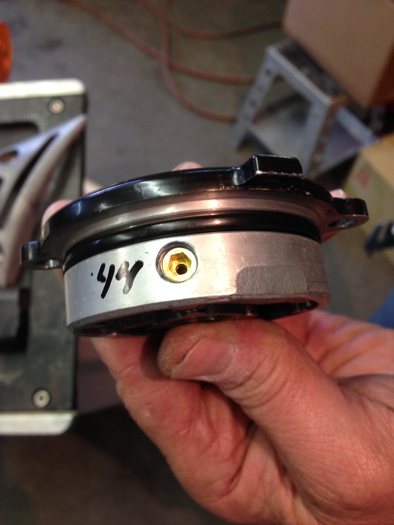
I've found that maybe the best place to measure temperature, is the center of the oil filter cap, with a infrared thermometer. Can do it while riding, with cruise control. Even uphill, 4th gear, full throttle, 7200RPM. (I will advise against this tactic, for safety reasons)
The Specs call for,
10W40 (I assume petroleum) probably does not matter if you have SYNTHETIC
194 degrees F., thats 90 degrees C. to you WILLY's.
4000 RPM
Correct.
I beleive, I have found a way to IMPROVE IT. After 2 1/2--3 years.
STOP THE LEAKAGE!!!!!!!!!!!!!!!!!!!!!!!!!!!!!!!!!
Willys wanted MORE, I wanted LESS. GO FIGURE!
1987 KL650-A1
64,160 MILES
Kawasaki 10W40 petroleum
13 PSI @ 194 f. @4000RPM
IT was MORE!
pdwestman